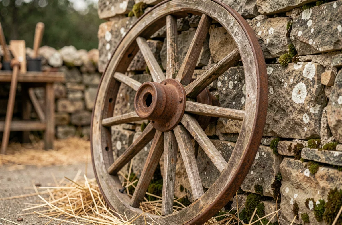
A wheel converts a force applied at its rim into rotation around a fixed axis, the axle. This wheel-and-axle combination is a simple machine in the lever family, where the difference between the wheel’s and axle’s radii determines the mechanical advantage. Understanding this mechanism means looking beyond friction reduction to examine the actual forces at the contact point, the geometry of the profiles, and the energy trade-offs inherent in every wheel.
Rolling resistance: the real energy cost of a rotating wheel
A wheel does not eliminate friction; it transforms it. At the contact point between the wheel and the ground, both surfaces deform. This deformation, however slight in a rigid material, dissipates energy as heat. This is rolling resistance.
On a tire, the contact patch compresses and then rebounds with each rotation. Rubber returns less energy than it absorbs during deformation: this is the material’s hysteresis. The more flexible the tire, the wider the contact patch and the greater the energy losses.
Research conducted by Queen Mary University of London highlights that reducing rolling resistance involves a direct trade-off with tire grip and lifespan. A very rigid tire rolls with less energy loss, but offers less grip and wears differently. A flexible tire grips the road better but consumes more energy. The detailed analysis of how a wheel works on Miss Deux Roues explores these trade-offs in a two-wheeler context, where every watt counts.
ISO 28580 governs the measurement of rolling resistance in tires, while the European regulation on the ecodesign of sustainable products encourages manufacturers to publish this data. This is no minor consideration: it directly affects a vehicle’s energy consumption.
Transmitting motion through the wheel-and-axle system
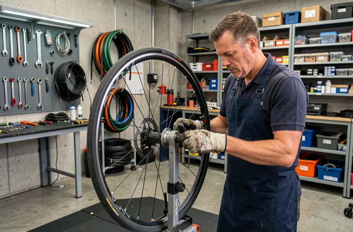
The wheel-and-axle system works like a rotating lever. The wheel acts as the long lever arm, and the axle as the short one. When a force is applied at the wheel’s rim, the torque transmitted to the axle is multiplied by the ratio of the wheel’s radius to the axle’s radius.
In practical terms, the larger the wheel is relative to the axle, the less force is required. A door handle illustrates this principle: your hand travels along a wide arc on the handle (the wheel), while the internal mechanism (the axle) turns through a short arc but generates enough torque to operate the latch.
The reverse arrangement is also used. When the driving force is applied to the axle, the wheel’s rim rotates faster, but with less torque. Fans, spin dryers, and foot-powered grinding wheels use this configuration.
Gear ratio in a gear train
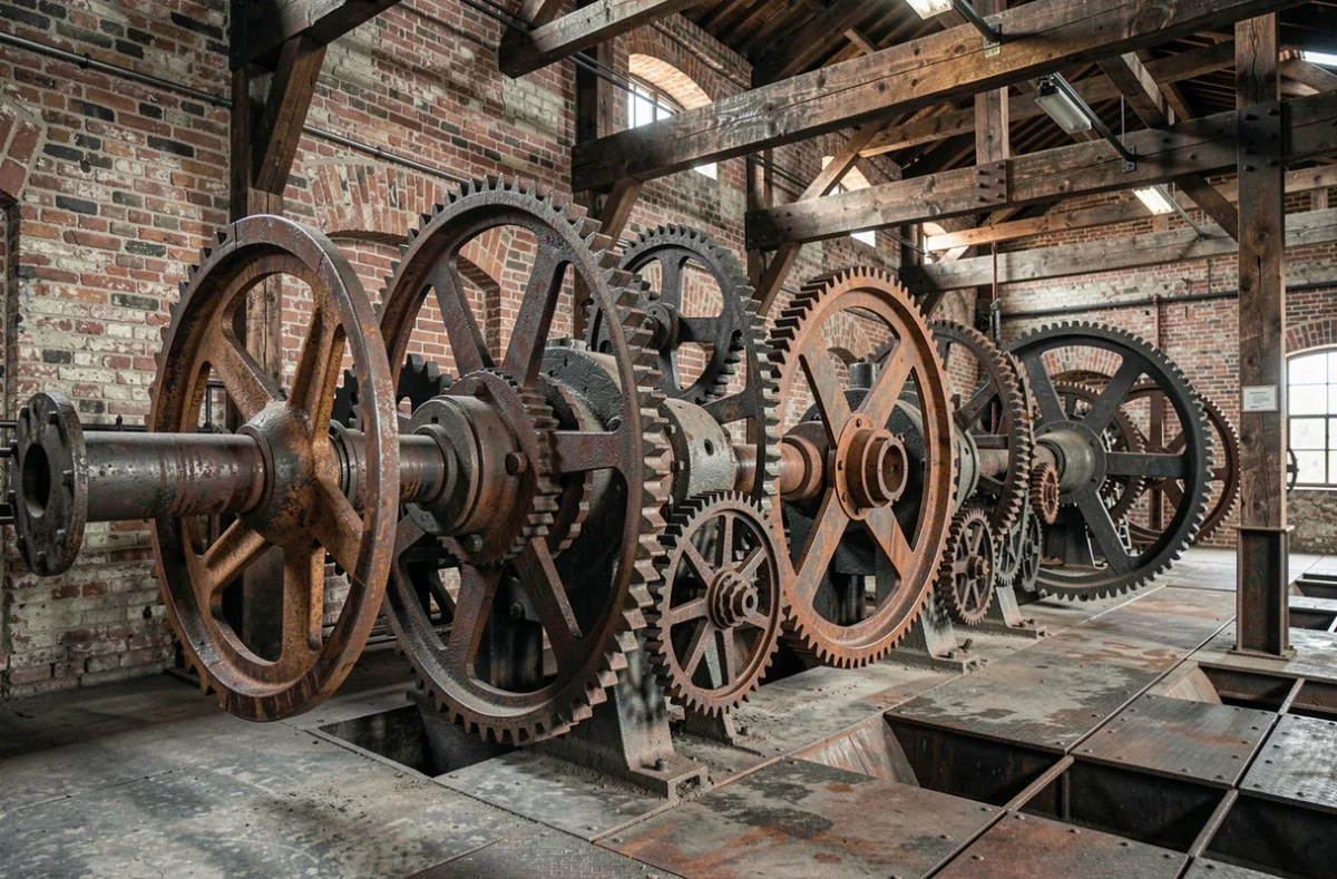
When several toothed wheels are connected, the gear ratio is calculated by multiplying the individual ratios. A gear pair in which the driving gear has fewer teeth than the driven gear reduces speed and increases torque. The ratio is determined precisely by the number of teeth, ensuring constant transmission without slippage.
- The module (the ratio of the pitch diameter to the number of teeth) must be the same for both gears to mesh correctly.
- The pitch diameter determines the distance between the two shafts and affects the mechanism’s overall size.
- Tooth quality (involute profile and surface finish) affects the gear’s efficiency, noise, and lifespan.
Conical profile of railway wheels and guidance on rails
Railway wheels are not cylindrical. Their treads have a conical profile, with a slightly larger diameter on the inside (toward the flange) than on the outside. On a rigid axle, where the two wheels are fixed together, a lateral shift changes each wheel’s effective rolling radius.
If the axle shifts to the right, the right wheel rolls on a larger radius and therefore covers more distance per revolution. The left wheel, rolling on a smaller radius, covers less distance. This asymmetry naturally creates a restoring torque that steers the axle back toward the center of the track.
Yaw instability above a critical speed
This self-centering mechanism has its limits. At low speeds, lateral oscillation (the axle’s sinusoidal movement along the rails) naturally dies down. Above a certain speed, however, it can grow instead. This is known as yaw, or hunting oscillation.
Stability depends on the wheel’s exact profile, the wheel-rail contact forces (which include microscopic longitudinal and lateral slips), and the suspension design. The cone alone does not guarantee stability: the bogie as a whole, with its springs and dampers, keeps the system’s behavior within a safe range at high speeds.
Drive wheels, freewheels, and kinetic energy storage
Any rotating wheel stores kinetic energy in proportion to its moment of inertia and the square of its angular velocity. A heavy wheel with mass concentrated at its rim (like a flywheel) stores more energy than a lightweight wheel rotating at the same speed.
This property is used in mechanical flywheels to smooth out engine fluctuations, as well as in braking energy recovery systems. By contrast, a free-rolling wheel (a non-driven wheel) simply follows the motion imposed by the ground, with resistance limited to rolling resistance and axle friction.
- A drive wheel transmits engine torque to the ground through grip. If the torque exceeds the grip limit, the wheel spins.
- A steering wheel changes the steering angle and therefore the vehicle’s path, without necessarily being driven.
- A flywheel uses mass concentrated at its rim to store and release rotational kinetic energy.
- On a bicycle, the freewheel in the rear hub allows the wheel to spin faster than the crankset without turning the pedals backward.
The wheel’s mechanism is based on a geometric principle—the difference in radius between the rim and the axle—that applies in radically different contexts, from a bicycle hub to a railway bogie. What changes from one application to another are the trade-offs: grip versus efficiency, stability versus lightness, energy storage versus responsiveness. Every wheel is an engineering compromise, tailored to a specific set of requirements.